Tower Crane
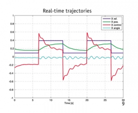
The control goal: to track a trajectory and not to swing the load
The three-dimensional laboratory model of tower crane corresponds to a modern structure of cranes that give the best combination of height and lifting capacity. The laboratory model is a highly nonlinear MIMO system equipped with a dedicated system of sensors – unique 2D angle measuring unit.
Every tower crane consists of the jib and counter-jib. Both are mounted to the turntable, where the slewing bearing and slewing machinery are located. The counter-jib carries a counterweight and the jib suspends the load from the trolley. In our model the turntable is located at the top of the tower – a special plastic-metal slewing ring is used.
 The system is fully integrated with MATLAB/ Simulink and operates in the real-time. A number of pre-programmed control experiments are included. They constitute a proper basis to construct own new algorithms of a user. The rapid prototyping of real control algorithms becomes an easy task (none C code writing is required). There are three control drives (the DC motor equipped with a gear) and five angular-position sensors (encoders). The jibs rotate driven by the first powerful drive. The trolley on the jib rail with an adjustable clearance is pushed back and forth by the transmission belt and the second drive. The lifting load is operated by the third drive. The typical control goal is to track a desired three-dimensional trajectory (i.e. operate the load in a prescribed manner) and simultaneously keep the load at the minimal amplitude of swinging.
 Hardware:
- 3 DC motors equipped with gears PWM controlled
- position sensors: incremental encoders
- power interface
- RT-DAC/USB I/O external board (PWM control and encoder logics are stored in a XILINX chip)
Dimensions:
600x1200x1600 mm (W/L/H)